How to Prevent Mechanical Seal Failure: Common Causes, Warning Signs & Solutions
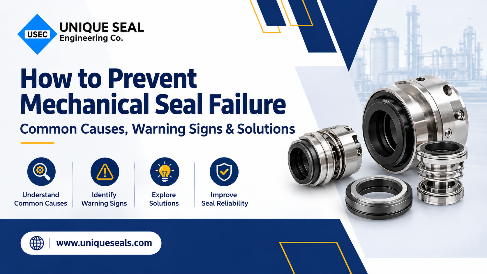
In rotating equipment such as centrifugal pumps, mixers, and compressors, mechanical seals are the primary barrier protecting your plant from fluid leakage, toxic emissions, and unplanned downtime. Despite their precision engineering, premature seal failure remains the single most common cause of pump maintenance shutdowns. Replacing a compromised seal without diagnosing why it failed guarantees repeated breakdowns. Preventing mechanical seal failure requires recognizing early warning indicators, identifying the true root causes, and applying systematic reliability practices.
Early Warning Signs of Mechanical Seal Failure
Mechanical seals rarely fail without giving off operational symptoms first. Catching these early warning signals allows maintenance teams to schedule planned intervention before catastrophic shaft or bearing damage occurs:
• Steady or Intermittent Weeping: Dripping from the gland drain or atmospheric side indicates primary face separation, cracked faces, or secondary O-ring degradation.
• Squealing or Chirping Noises: High-pitched sounds during startup or operation indicate insufficient lubrication, dry running, or face vapor flashing.
• Excessive Local Heat: A hot seal chamber or scorched gland plate signals friction overloads, inadequate flush fluid, or dead-heading.
• Black Powder or Sludge Accumulation: Carbon dust collecting around the gland exterior is a clear indicator of dry face contact or severe hydraulic over-pressurization.
• Elevated Pump Vibration: High radial vibration shakes the seal assembly, breaching face flatness and degrading secondary elastomers.
The 4 Most Common Causes of Mechanical Seal Failure
1. Dry Running and Fluid Film Vaporization
Mechanical seal faces rely on a microscopic hydrodynamic fluid film—often just 1 micron thick—for face lubrication and heat dissipation. When a pump runs dry, cavitates, or operates with entrained air, this fluid film instantly boils off. The resulting friction causes thermal shock, leading to cracked Silicon Carbide faces, blistered carbon rings, and complete leakage within minutes.
2. Installation and Alignment Errors
Over 60% of component seal failures trace back to human error during assembly: incorrect spring compression (which generates severe friction or face separation), pinched or twisted O-rings that create bypass channels, and excessive shaft radial runout (> 0.05 mm) that prevents seal faces from tracking evenly.
3. Chemical Attack and Elastomer Swelling
Exposing secondary elastomers (O-rings, gaskets, wedges) to incompatible fluids causes swelling, softening, or embrittlement. A swollen dynamic O-ring causes 'seal hang-up,' preventing springs from pushing the primary faces together as they wear. In severe chemical environments, improper metallurgy can also lead to pitting corrosion on springs or sleeves.
4. Particulate Abrasion and Clogging
Abrasive slurries, suspended solids, or crystallizing media penetrate the seal face gap, scoring precision-lapped surfaces. Particulates also collect around coil springs, clogging them and preventing necessary axial compensation.
Proven Solutions to Prevent Mechanical Seal Failure
1. Standardize on Pre-Assembled Cartridge Seals
Upgrading from loose component seals to pre-set cartridge seals eliminates the primary source of installation mistakes. Cartridge seals come factory-assembled with internal sleeves, glands, and spacer clips, ensuring proper spring preload, square face alignment, and zero contaminant exposure during mounting.
2. Vent and Flood the Seal Chamber Prior to Startup
Never start a pump dry. Before energizing the motor, always crack open the seal gland’s high-point vent to release trapped air and ensure the seal chamber is completely flooded with process liquid. Verify that your suction line is flooded and Net Positive Suction Head Available (NPSHa) exceeds required levels (NPSHr).
3. Optimize Auxiliary Flush Piping Plans
Proper Auxiliary Flush Piping Plans (such as API 682 Plan 11, 23, or 53A/B) maintain thermal and chemical stability across the seal chamber. Use Plan 11/13 to dissipate heat, Plan 62 external quench to eliminate crystallization, and dual pressurized systems with barrier fluid held 1.5 to 2.0 bar above stuffing box pressure for toxic or abrasive slurries.
4. Match Materials Using the STAMPS Method
Verify chemical and thermal compatibility across all four seal elements (rotary face, stationary seat, secondary elastomers, and metal hardware) using the STAMPS criteria: Size, Temperature, Application, Media, Pressure, and Safety. For abrasive duties, specify hard-on-hard face combinations (Sintered Silicon Carbide vs. Tungsten Carbide) and corrosion-resistant springs like Hastelloy C-276.
Final Thoughts
Preventing mechanical seal failure requires treating the seal as part of a complete hydraulic and mechanical system. By verifying operating conditions, maintaining proper fluid flush plans, and selecting balanced cartridge assemblies matched to your process chemistry, your plant can prevent costly leaks, safeguard equipment, and maximize operational uptime.